
During the Apollo flights to the Moon, the astronauts observed the spacecraft’s orientation on a special instrument
called the FDAI (Flight Director / Attitude Indicator).
This instrument showed the spacecraft’s attitude—its orientation—by rotating a ball.
This ball was nicknamed the “8-ball” because it was black (albeit only on one side).
The instrument also acted as a flight director, using three yellow needles to indicate how the astronauts should maneuver
the spacecraft. Three more pointers showed how fast the spacecraft was rotating.
 with the case removed. This FDAI is on its side to avoid crushing the needles.")
An Apollo FDAI (Flight Director/Attitude Indicator) with the case removed. This FDAI is on its side to avoid crushing the needles.
Since the spacecraft rotates along three axes (roll, pitch, and yaw), the ball also rotates along three axes.
It’s not obvious how the ball can rotate to an arbitrary orientation while remaining attached.
In this article, I look inside an FDAI from Apollo that was repurposed for a Space Shuttle simulator1 and explain how it operates. (Spoiler: the ball mechanism is firmly attached
at the “equator” and rotates in two axes. What you see is two hollow shells around the ball mechanism that spin around the third axis.)
The FDAI in Apollo
For the missions to the Moon, the Lunar Module had two FDAIs, as shown below: one on the left for the Commander (Neil Armstrong in Apollo 11) and
one on the right for the Lunar Module Pilot (Buzz Aldrin in Apollo 11).
With their size and central positions, the FDAIs dominate the instrument panel, a sign of their importance.
(The Command Module for Apollo also had two FDAIs, but with a different design; I won’t discuss them here.2)

Each Lunar Module FDAI could display inputs from multiple sources, selected by switches on the panel.3 The ball could display attitude from either the
Inertial Measurement Unit
or from the backup Abort Guidance System, selected by the “ATTITUDE MON” toggle switch next to either FDAI.
The pitch attitude could also be supplied by an electromechanical unit called ORDEAL (Orbital Rate Display Earth And Lunar)
that simulates a circular orbit.
The error indications came from the Apollo Guidance Computer, the Abort Guidance System, the landing radar,
or the rendezvous radar (controlled by the “RATE/ERROR MON” switches).
The pitch, roll, and yaw rate displays were driven by the Rate Gyro Assembly (RGA).
The rate indications were scaled by a switch below the FDAI, selecting 25°/sec or 5°/sec.
The FDAI mechanism
The ball inside the indicator shows rotation around three axes.
I’ll first explain these axes in the context of an aircraft, since the axes of a spacecraft are more arbitrary.4
The roll axis indicates the aircraft’s angle if it rolls side-to-side along its axis of flight, raising one wing
and lowering the other.
Thus, the indicator shows the tilt of the horizon as the aircraft rolls.
The pitch axis indicates the aircraft’s angle if it pitches up or down, with the indicator showing the horizon
moving down or up in response.
Finally, the yaw axis indicates the compass direction that the aircraft is heading,
changing as the aircraft turns left or right.
(A typical aircraft attitude indicator omits yaw.)
I’ll illustrate how the FDAI rotates the ball in three axes, using an orange as an example.
Imagine pinching the horizontal axis between two fingers with your arm extended.
Rotating your arm will roll the ball counter-clockwise or clockwise (red arrow).
In the FDAI, this rotation is accomplished by a motor turning the frame that holds the ball.
For pitch, the ball rotates forward or backward around the horizontal axis (yellow arrow).
The FDAI has a motor inside the ball to produce this rotation.
Yaw is a bit more difficult to envision: imagine hemisphere-shaped shells attached to the top and bottom shafts.
When a motor rotates these shells (green arrow), the hemispheres will rotate, even though
the ball mechanism (the orange) remains stationary.

A sphere, showing the three axes.
The diagram below shows the mechanism inside the FDAI.
The indicator uses three motors to move the ball.
The roll motor is attached to the FDAI’s frame, while the pitch and yaw motors are inside the ball.
The roll motor rotates the roll gimbal through gears, causing the ball to rotate clockwise or counterclockwise.
The roll gimbal is attached to the ball mechanism at two points along the “equator”;
these two points define the pitch axis.
Numerous wires on the roll gimbal enter the ball along the pitch axis.
The roll control transformer provides position feedback, as will be explained below.

The main components inside the FDAI.
Removing the hemispherical shells reveals the
mechanism inside the ball.
When the roll gimbal is rotated, this mechanism rotates with it.
The pitch motor causes the ball mechanism to rotate around the pitch axis.
The yaw motor and control transformer are not visible in this photo; they are behind the pitch components, oriented
perpendicularly.
The yaw motor turns the vertical shaft, with
the two hemisphere shells attached to the top and bottom of the shaft.
Thus, the yaw motor rotates the ball shells around the yaw axis, while the mechanism itself
remains stationary.
The control transformers for pitch and yaw provide position feedback.

The components inside the ball of the FDAI.
Why doesn’t the wiring get tangled up as the ball rotates?
The solution is two sets of slip rings to implement the electrical connections.
The photo below shows the first slip ring assembly, which handles rotation around the roll axis.
These slip rings connect the stationary part of the FDAI to the
rotating roll gimbal.
The vertical metal brushes are stationary; there are 23 pairs of brushes, one for each connection to the ball mechanism.
Each pair of brushes contacts one metal ring on the striped shaft, maintaining contact as the shaft rotates.
Inside the shaft, 23 wires connect the circular metal contacts to the roll gimbal.

The slip ring assembly in the FDAI.
A second set of slip rings inside the ball handles rotation around the pitch axis.
These rings provide the electrical connection between the
wiring on the roll gimbal and the ball mechanism.
The yaw axis does not use slip rings since only the hemisphere shells rotate around the yaw axis;
no wires are involved.
Synchros and the servo loop
In this section, I’ll explain how the FDAI is controlled by synchros and servo loops.
In the 1950s and 1960s, the standard technique for transmitting a rotational signal electrically was through a synchro.
Synchros were used for everything from rotating an instrument indicator in avionics to rotating the gun on a navy battleship.
A synchro produces an output that depends on the shaft’s rotational position, and transmits this output signal
on three wires.
If you connect these wires to a second synchro, you can use the first synchro to control the second one:
the shaft of the second synchro will rotate to the same angle as
the first shaft.
Thus, synchros are a convenient way to send a control signal electrically.
The photo below shows a typical synchro, with the input shaft on the top and five wires
at the bottom: two for power and three for the output.

A synchro transmitter.
Internally, the synchro has a rotating winding called the rotor that is driven with 400 Hz AC.
Three fixed stator windings provide the three AC output signals. As the shaft rotates, the voltages of the
output signals change, indicating the angle.
(A synchro resembles a transformer with three variable secondary windings.)
If two connected synchros have different angles, the magnetic fields create a torque that rotates the shafts into alignment.

The schematic symbol for a synchro transmitter or receiver.
The downside of synchros is that they don’t produce a lot of torque.
The solution is to use a more powerful motor, controlled by the synchro and a feedback loop called a servo loop.
The servo loop drives the motor in the appropriate direction to eliminate the error between the desired position and the
current position.
The diagram below shows how the servo loop is constructed from a combination of electronics and mechanical components.
The goal is to rotate the output shaft to an angle that exactly matches the input angle,
specified by the three synchro wires.
The control transformer compares the input angle and the output shaft position, producing an error signal.
The amplifier uses this error signal to drive the motor in the appropriate direction until the error signal drops to zero.
To improve the dynamic response of the servo loop, the tachometer signal is used as a negative feedback voltage.
The feedback slows the motor as the system gets closer to the right position, so the motor doesn’t overshoot the position and oscillate.
(This is sort of like a PID controller.)

This diagram shows the structure of the servo loop, with a feedback loop ensuring that the rotation angle of the output shaft matches the input angle.
A control transformer
is similar to a synchro in appearance and construction, but the rotating shaft operates as an input, not the output.
In a control transformer, the three stator windings receive the inputs and the rotor winding provides the error output.
If the rotor angle of the synchro transmitter and control transformer are the same, the signals cancel out and there is
no error voltage.
But as the difference between the two shaft angles increases, the rotor winding produces an error signal. The phase of the
error signal indicates the direction of the error.
In the FDAI, the motor is a special motor/tachometer, a device that was often used in avionics servo loops.
This motor is more complicated than a regular electric motor.
The motor is powered by 115 volts AC at 400 hertz, but this won’t spin the motor on its own.
The motor also has two low-voltage control windings. Energizing the control windings with the proper phase causes the
motor to spin in one direction or the other.
The motor/tachometer unit also contains a tachometer to measure its speed for the feedback loop.
The tachometer is driven by another 115-volt AC winding and generates a low-voltage AC signal that is proportional
to the motor’s rotational speed.
 to the one in the FDAI.")
A motor/tachometer similar (but not identical) to the one in the FDAI.
The photo above shows a motor/tachometer with the rotor removed.
The unit has many wires because of its multiple windings.
The rotor has two drums. The drum on the left, with the spiral stripes, is for the motor. This drum is a “squirrel-cage rotor”,
which spins due to induced currents.
(There are no electrical connections to the rotor; the drums interact with the windings through magnetic fields.)
The drum on the right is the tachometer rotor; it induces a signal in the output winding proportional to the speed due to eddy currents.
The tachometer signal is at 400 Hz like the driving signal, either in phase or 180º out of phase, depending on the direction
of rotation.
For more information on how a motor/tachometer works, see my teardown.
The amplifiers
The FDAI has three servo loops—one for each axis—and each servo loop has a separate control transformer, motor, and amplifier.
The photo below shows one of the three amplifier boards. The construction is unusual and somewhat chaotic,
with some components stacked on top of others to save space.
Some of the component leads are long and protected with clear plastic sleeves.5
The cylindrical pulse transformer in the middle has five colorful wires coming out of it.
At the left are the two transistors that drive the motor’s control windings, with two capacitors between them.
The transistors are mounted on a heat sink that is screwed down to the case of the amplifier assembly for cooling.
Each amplifier is connected to the FDAI through seven wires with pins that
plug into the sockets on the right of the board.6

One of the three amplifier boards. At the right front of the board, you can see a capacitor stacked on top of a resistor. The board is shiny because it is covered with conformal coating.
The function of the board is to amplify the error signal so the motor rotates in the appropriate direction.
The amplifier also uses the tachometer output from the motor unit to slow the motor as the error signal decreases, preventing
overshoot.
The inputs to the amplifier are 400 hertz AC signals, with the magnitude indicating the amount of error or speed and the
phase indicating the direction.
The two outputs from the amplifier drive the two control windings of the motor, determining which direction the motor rotates.
The schematic for the amplifier board is below. 7
The two transistors on the left amplify the error and tachometer signals, driving the pulse transformer.
The outputs of the pulse transformer will have opposite phases, driving the output transistors for opposite halves of
the 400 Hz cycle.
This activates the motor control winding, causing the motor to spin in the desired direction.8

The schematic of an amplifier board.
History of the FDAI
Bill Lear, born in 1902, was a prolific inventor with over 150 patents,
creating everything from the 8-track tape to the Learjet, the iconic
private plane of the 1960s.
He created multiple companies in the 1920s as well as inventing one of the first car radios for Motorola before starting Lear Avionics,
a company that specialized in aerospace instruments.9
Lear produced innovative aircraft instruments and flight control systems such as
the F-5 automatic pilot, which received a trophy as the “greatest aviation achievement in America” for 1950.
Bill Lear went on to solve an indicator problem for the Air Force:
the supersonic F-102 Delta Dagger interceptor (1953) could climb at steep angles, but existing
attitude indicators could not handle nearly vertical flight.
Lear developed a remote two-gyro platform that drove the cockpit indicator while avoiding “gimbal lock” during vertical
flight.
For the experimental X-15 rocket-powered aircraft (1959), Lear improved this indicator to handle three axes:
roll, pitch, and yaw.
Meanwhile, the Siegler Corporation started in 1950 to manufacture space heaters for homes. A few years later, Siegler was acquired
by John Brooks, an entrepreneur who was enthusiastic about acquisitions. In 1961, Lear Avionics became his latest acquisition, and
the merged company was called Lear Siegler Incorporated, often known as LSI.
(Older programmers may know Lear Siegler through the ADM-3A, an inexpensive video display terminal from 1976 that
housed the display and keyboard in a stylish white case.)
The X-15’s attitude indicator became the basis of the indicator for the F-4 fighter plane
(the ARU/11-A).
Then, after “a minimum of modification“,
the attitude-director indicator was used in the Gemini space program.
In total, Lear Siegler provided 11 instruments in the Gemini instrument panel, with the attitude director the most important.
Next, Gemini’s indicator was modified to become the FDAI (flight director-attitude indicator) in the Lunar Module for Apollo.10
Lear Siegler provided numerous components for the Apollo program, from a directional gyro for the Lunar Rover
to the electroluminescent display for the Apollo Guidance Computer’s Display/Keyboard (DSKY).
")
An article titled “LSI Instruments Aid in Moon Landing” from LSI’s internal LSI Log publication, July 1969. (Click for a larger version.)
In 1974, Lear Siegler obtained a contract to develop the Attitude-Director Indicator (ADI) for the Space Shuttle, producing
a dozen ADI units for the Space Shuttle.
However, by this time, Lear Siegler was losing enthusiasm for low-volume space avionics.
The Instrument Division president said that “the business that we were in was an engineering business and engineers
love a challenge.”
However, manufacturing refused to deal with the special procedures required for space manufacturing,
so the Shuttle units were built by the engineering department.
Lear Siegler didn’t bid on later Space Shuttle avionics and the Shuttle ADI became its last space product.
In the early 2000s, the Space Shuttle’s instruments were upgraded to a “glass cockpit” with 11 flat-panel displays known
as the Multi-function Electronic Display System (MEDS).
The MEDS was produced by Lear Siegler’s long-term competitor, Honeywell.
Getting back to Bill Lear, he wanted to manufacture aircraft, not just aircraft instruments, so
he created the Learjet, the first mass-produced business jet.
The first Learjet flew in 1963, with over 3000 eventually delivered.
In the early 1970s, Lear designed a steam turbine automobile engine. Rather than water, the turbine
used a secret fluorinated hydrocarbon called “Learium”. Lear had visions of thousands of low-pollution “Learmobiles“, but the engine failed
to catch on.
Lear had been on the verge of bankruptcy in the 1960s; one of his VPs explained that
“the great creative minds can’t be bothered with withholding taxes and investment credits and all this crap”.
But by the time of his death in 1978, Lear had a fortune estimated at $75 million.
Comparing the ARU/11-A and the FDAI
Looking inside our FDAI sheds more details on the evolution of Lear Siegler’s attitude directors.
The photo below compares the Apollo FDAI (top) to the earlier ARU/11-A used in the F-4 aircraft (bottom).
While the basic mechanism and the electronic amplifiers are the same between the two indicators, there are
also substantial changes.
 with an ARU-11/A (bottom). The amplifier boards and needles have been removed from the FDAI.")
Comparison of an FDAI (top) with an ARU-11/A (bottom). The amplifier boards and needles have been removed from the FDAI.
The biggest difference between the ARU-11/A indicator and the FDAI is that the electronics for the ARU-11/A
are in a separate module that was plugged into the back of the indicator, while the FDAI includes the electronics
internally, with boards mounted on the instrument frame.
Specifically, the ARU-11/A has a separate unit containing a multi-winding transformer, a power supply board,
and three amplifier boards (one for each axis), while the FDAI contains these components internally.
The amplifier boards in the ARU-11/A and the FDAI are identical, constructed from germanium transistors rather than
silicon.11
The unusual 11-pin transformers are also the same.
However, the power supply boards are different, probably because the boards also contain scaling resistors
that vary between the units.12
The power supply boards are also different shapes to fit the available space.
The ball assemblies of the ARU/11-A and the FDAI are almost the same, with the same motor assemblies and slip ring
mechanism.
The gearing has minor changes. In particular, the FDAI has two plastic gears, while the ARU/11-A uses
exclusively metal gears.
The ARU/11-A has a patented pitch trim feature that was
mostly—but not entirely—removed from the Apollo FDAI.
The motivation for this feature is that an aircraft in level flight will be pitched up a few degrees, the “angle of attack”.
It is desirable for the attitude indicator to show the aircraft as horizontal, so a pitch trim knob allows the
angle of attack to be canceled out on the display.
The problem is that if you fly your fighter plane vertically, you want the indicator to show precisely
vertical flight, rather than applying the pitch trim adjustment.
The solution in the ARU-11/A is a special 8-zone potentiometer on the pitch axis that will apply the pitch trim
adjustment in level flight but not in vertical flight, while providing a smooth transition between the regions.
This special potentiometer is mounted inside the ball of the ARU-11/A.
However, this pitch trim adjustment is meaningless for a spacecraft, so it is not implemented in the Apollo
or Space Shuttle instruments.
Surprisingly, the shell of the potentiometer still exists in our FDAI, but without the potentiometer itself or the
wiring.
Perhaps it remained to preserve the balance of the ball.
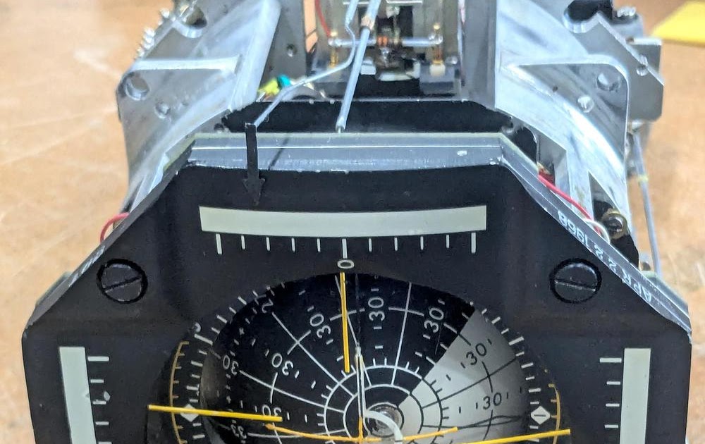
In the photo below, the cylindrical potentiometer shell is indicated by an arrow. Note the holes in the front
of the shell; in the ARU-11/A, the potentiometer’s wiring terminals protrude through these holes, but in the
FDAI, the holes are covered with tape.

Inside the ball of the FDAI. The potentiometer shell is indicated with an arrow.
Finally, the mounting of the ball hemispheres is slightly different.
The ARU/11-A uses four screws at the pole of each hemisphere.
Our FDAI, however, uses a single screw at each pole; the screw is tightened with a Bristol Key, causing the
shaft to expand and hold the hemisphere in place.
To summarize, the Apollo FDAI occupies a middle ground: while it isn’t simply a repurposed ARU-11/A, neither is
it a complete redesign.
Instead, it preserves the old design where possible, while stripping out undesired features such as pitch trim.
The separate amplifier and mechanical units of the ARU/11-A were combined to form the larger FDAI.
Differences from Apollo
The FDAI that we examined is a special unit:
it was originally built for Apollo but was repurposed for a Space Shuttle simulator.
Our FDAI is labeled Model 4068F, which is a Lunar Module part number.
Moreover, the FDAI is internally stamped with the date “Apr. 22 1968”, over a year before the first Moon landing.
However, a closer look shows that several key components were modified to make the Apollo FDAI work in the Shuttle Simulator.14
The Apollo FDAI (and the Shuttle ADI) used resolvers as inputs to control the ball, while our FDAI uses synchros.
(Resolvers and synchros are similar, except resolvers use sine and cosine inputs, 90° apart, on two wire pairs, while
synchros use three inputs, 120° apart, on three wires.)
NASA must have replaced the three resolver control transformers in the FDAI with synchro control transformers for use
in the simulator.
The Apollo FDAI used electroluminescent lighting for the display, while ours uses eight small incandescent bulbs.
The metal case of our FDAI has a Dymo embossed tape label “INCANDESCENT
LIGHTING”, alerting users to the change from Apollo’s illumination.
Our FDAI also contains a step-down transformer to convert the 115 VAC input into 5 VAC to power the bulbs,
while the Shuttle powered its ADI illumination directly from 5 volts.
The dial of our FDAI was repainted to match the dial of the Shuttle FDAI.
The Apollo FDAI had red bands on the left and right of the dial.
A close examination of our dial shows that black paint was carefully applied over the red paint, but a few specks of
red paint are still visible (below).
Moreover, the edges of the lines and the lozenge show slight unevenness from the repainting.
Second, the Apollo FDAI had the text “ROLL RATE”, “PITCH RATE”, and “YAW RATE” in white next to the needle scales.
In our FDAI, this text has been hidden by black paint to match the Shuttle display.13
Third, the Apollo LM FDAI had a crosshair in the center of the instrument, while our FDAI has a white U-shaped
indicator, the same as the Shuttle (and the Command Module’s FDAI).
Finally, the ball of the Apollo FDAI has red circular regions at the poles to warn of orientations that can cause
gimbal lock. Our FDAI (like the Shuttle) does not have these circles. We couldn’t see any evidence that these
regions were repainted, so we suspect that our FDAI has Shuttle hemispheres on the ball.

A closeup of the dial on our FDAI shows specks of red paint around the dial markings. The color is probably Switzer DayGlo Rocket Red.
Our FDAI has also been modified electrically.
Small green connectors (Micro-D MDB1) have been added between the slip rings and the motors, as well as on the gimbal arm.
We think these connectors were added post-Apollo, since they are attached somewhat sloppily with glue and don’t
look flight-worthy.
Perhaps these connectors were added to make disassembly and modification easier.
Moreover, our FDAI has an elapsed time indicator, also mounted with glue.
The back of our FDAI is completely different from Apollo.
First, the connector’s pinout is completely different.
Second, each of the six indicator needles has a mechanical adjustment as well as a trimpot (details).
Finally, each of the three axes has an adjustment potentiometer.
The Shuttle’s ADI (Attitude Director Indicator)
Each Space Shuttle had three ADIs (Attitude Director Indicators), which were very similar to the Apollo FDAI, despite
the name change.
The photo below shows the two octagonal ADIs in the forward flight deck, one on the left in front of the Commander,
and one on the right in front of the Pilot.
The aft flight deck station had a third ADI.15
. The ADIs are indicated with arrows. The photo is from the National Archives.")
Our FDAI appears to have been significantly modified for use in the Shuttle simulator, as described above.
However, it is much closer to the Apollo FDAI than the ADI used in the Shuttle, as I’ll show in this section.
My hypothesis is that the simulator was built before the Shuttle’s ADI was created, so the Apollo FDAI was pressed
into service.
The Shuttle’s ADI was much more complicated electrically than the Apollo FDAI and our FDAI, providing improved
functionality.16
For instance, while the Apollo FDAI had a simple “OFF” indicator flag to show that the indicator had lost power,
the Shuttle’s ADI had extensive error detection.
It contained voltage level monitors to check its five power supplies. (The Shuttle ADI used three DC power sources
and two AC power sources, compared to the single AC supply for Apollo.)
The Shuttle’s ADI also monitored the ball servos to detect position errors. Finally, it received an external “Data OK” signal.
If a fault was detected by any of these monitors, the “OFF” flag was deployed to indicate that the ADI could not
be trusted.
The Shuttle’s ADI had six needles, the same as Apollo, but the Shuttle used feedback to make the positions more accurate.
Specifically, each Shuttle needle had a feedback sensor, a Linear Variable Differential Transformer (LVDT) that generates
a voltage based on the needle position.
The LVDT output drove a servo feedback loop to ensure that the needle was in the exact desired position.
In the Apollo FDAI, on the other hand, the needle input voltage drove a galvanometer, swinging the needle proportionally,
but there was no closed loop to ensure accuracy.
I assume that the Shuttle’s ADI had integrated circuit electronics to implement this new functionality, considerably
more modern than the germanium transistors in the Apollo FDAI.
The Shuttle probably used the same mechanical structures to rotate the ball, but I can’t confirm that.
Conclusions
The FDAI was a critical instrument in Apollo, indicating the orientation of the spacecraft in three axes.
It wasn’t obvious to me how the “8-ball” can rotate in three axes while still being securely connected to the
instrument.
The trick is that most of the mechanism rotates in two axes, while hollow hemispherical shells provide the
third rotational axis.
The FDAI has an interesting evolutionary history, from the experimental X-15 rocket plane and the F-4 fighter to
the Gemini, Apollo, and Space Shuttle flights.
Our FDAI has an unusual position in this history: since it was modified from Apollo to function in a Space Shuttle
simulator, it shows aspects of both Apollo and the Space Shuttle indicators.
It would be interesting to compare the design of a Shuttle ADI to the Apollo FDAI, but I haven’t been able to find
interior photos of a Shuttle ADI (or of an unmodified Apollo FDAI).17
You can see a brief video of the FDAI in motion here. For more, follow me on
Bluesky (@righto.com),
Mastodon (@[email protected]),
or RSS. (I’ve given up on Twitter.)
I worked on this project with CuriousMarc, Mike Stewart, and Eric Schlapfer, so expect a
video at some point. Thanks to Richard for providing the FDAI.
I wrote about the F-4 fighter plane’s attitude indicator here.

Inside the FDAI. The amplifier boards have been removed for this photo.